Replacing track-rod-end ball joints
The Video Course teaches you everything about modern cars.
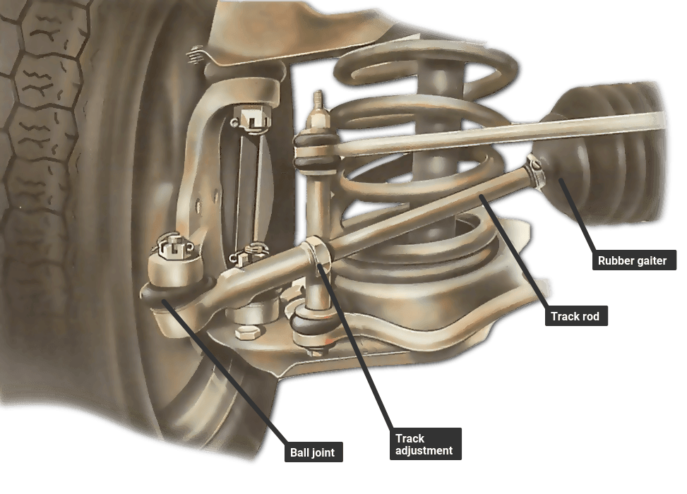
Track-rod-end ball joints are not adjustable on later cars. If they wear, you must replace them.
The rubber gaiters which protect the joints and retain their lubricating grease must also be replaced if they show signs of splitting, ageing or other damage.
Even if only one of the joints is worn, the joint on the opposite track-rod end should also be renewed.
Most ball joints are simply screwed on to the ends of the track rods, so replacing them is straightforward.
However, some cars, such as certain Renaults, Audis and VWs, have one-piece track rods with integral ball joints. In such cases the whole track rod must be replaced.
If your car has rack-and-pinion steering , make sure the steering wheel is turned only very slowly when the front wheels are off the ground .
Turning it rapidly can build up hydraulic pressure in the steering-rack housing, which may cause one or both rubber gaiters to burst.
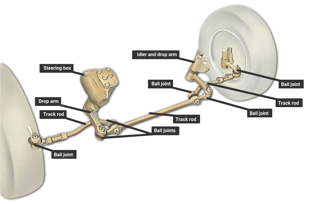
As you will need to work under the front of the car, jack up that end and support it on axle stands placed under chassis members.
Make sure that the handbrake is on firmly, and put chocks behind the rear wheels. Remove the front wheels.
The position of the ball joints on the track-rod ends determines the front-wheel 'track' — the amount of toe-in or toe-out. Care must be taken in fitting a new ball joint to see that it goes on in the same position as the old one. But in any case, take the car to a garage as soon as possible for a tracking check. Even a small amount of excessive toe-in or toe-out will cause rapid tyre wear, apart from affecting the steering handling.
Special rack-and-pinion systems
The type of steering rack and track rods fitted to some Audis and VWs varies from other systems.
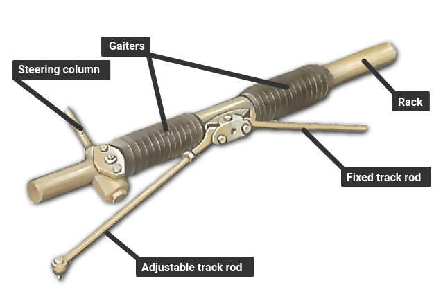
On one side the track rod is adjustable, and its ball joint can be replaced. On the other side there is a fixed-length track rod with an integral ball joint.
The fixed-length rod is replaced with an adjustable one as a service item. The ball joint can then be renewed in the normal way.
Other systems
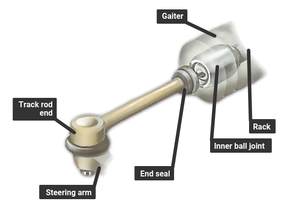
Other models have a more conventional rack, but it still has one non-adjustable, one-piece track rod. to replace this, you need to remove the rack gaiter.
The whole outer half of this Renault-type track rod is replaced, complete with its integral ball joint.
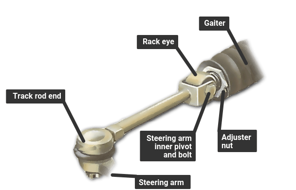
Releasing a ball joint
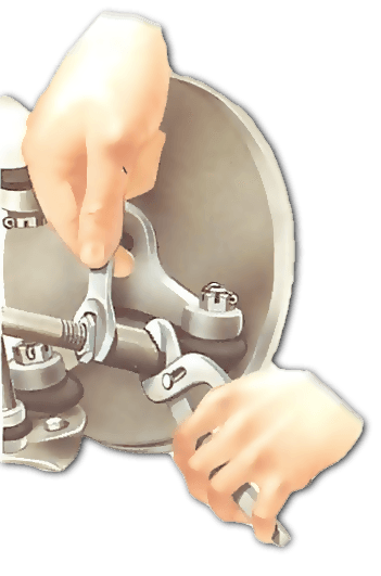
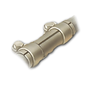
The ball joint usually screws on to the track rod and is held by a locknut, either on the rod or joint. Some ball joints are secured by a clamp around a tubular-ended track rod.
Slacken off the locknut or clamp. If the joint has 'flats' cast into its body, hold them with another spanner or self-locking grips to stop the joint turning as you unscrew the locknut: otherwise the turning force on the locknut may force the joint beyond its normal travel and damage it.
This does not matter if the joint is being renewed, but is important if you are simply replacing a rack gaiter and putting the same joint back on.
Such damage can cause the joint to fall apart in use.
Mark or measure the precise position of the ball joint on the track rod, so that it - or a new joint - can be replaced in exactly the same position later. This is because the front wheel toe-in setting (See Adjusting toe alignment on wheels ) is almost always adjusted by screwing the ball joint in or out, though there are a few exceptions. On some cars, adjustment is made by a rod threaded at both ends between the ball joint and the track rod. Do not slacken the inner locknut or alter the position of the rod.
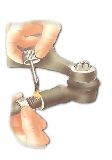
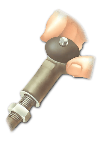
Ball joints which screw over a threaded track rod can be marked in several ways. The simplest is to screw the locknut back until it just touches the end of the ball joint, but does not lock it. Leave it there as a guide when reassembling.
Another way is to paint both thread and ball-joint body or count the threads visible between the end of the joint and where the threads end.
You can also wrap tape around the track rod to butt against the ball joint, or measure from the end of the joint to another fixed point, such as the end of the rack gaiter.
If the ball joint has a solid end which screws into the track rod, gauge its position by measuring the length of thread showing on the ball joint, or by counting the turns needed to unscrew it.
None of these methods is precise, however, and the toe-in setting must be checked by a garage as soon as possible.
Separating a ball joint
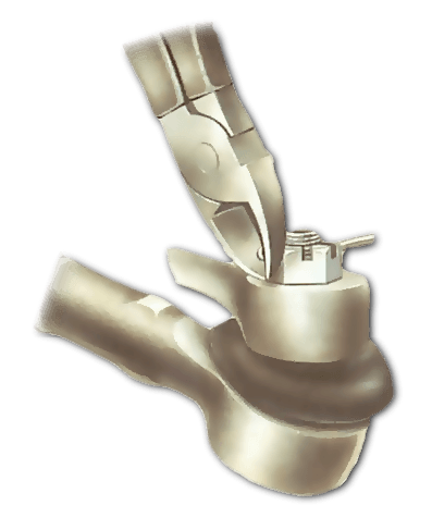
The joint is fixed to the steering arm by a self-locking nut or by a castellated nut and split pin.
Remove the split pin before unscrewing a castellated nut and always use a new split pin when you reassemble it later.
A self-locking nut can be screwed straight off, but a new one must be used when you replace the ball joint later. Never reuse an old self-locking nut - it is likely to work loose in time.
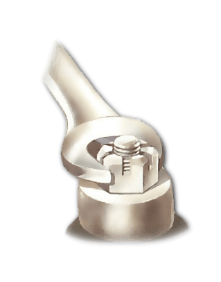
With the securing nut off - and any washer under it also removed - the ball joint can be separated from the steering arm. But the joint is a taper fit into the arm and requires some force to free it.
There are three ways to separate the ball joint and steering arm.
The best and easiest method is to use a scissor-action ball-joint separating tool . Fit it so that one arm bears against the steering arm and the other against the nut on the ball-joint stud .
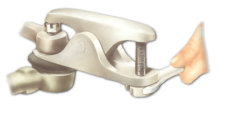
Tightening the bolt on the tool makes the arms close, and the one bearing against the stud forces the tapered shaft of the joint out of its tapered seating in the steering arm.
Another way is to hammer a special forked wedge between the body of the ball joint and the steering arm, again forcing them apart.
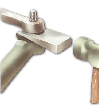
However, the wedge will almost certainly damage the rubber dust excluder on the joint, so use one only when you are fitting a new joint. On cars where the ball joint is above the arm, slacken the nut until it is at the end of the thread and place a jack underneath it. Adjust the jack so that it just supports the car's weight. Use two hammers to strike the sides of the steering arm simultaneously. This will spring the taper out of its seating.
Unscrewing the ball joint
Once the ball joint is separated from the steering arm, you can unscrew it from the track rod. Count the number of turns and use the same number to replace it, if there is no other way to mark its exact position for replacement later.
The Ultimate Car Mechanics video course
Learn everything about modern cars from our new video series.
Learn more >-
We build a Mazda MX5 Miata from scratch
We start by tearing down and then rebuilding the whole car.
-
Every part explained
There's ridiculous detail on every part. Clearly and easily explained.
-
All modeled in 3D
We've created the most detailed 3D model ever produced so we can show you everything working.
